Segments
Create, manage, and organize segments using the toolbar controls described below.
Steps
-
Add Segment
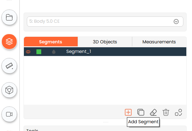
- Click the "Add Segment" button to create a new, easily identifiable segment in the segment table with its own unique color and name. The segment name can be renamed by double-clicking on a segment item.
- Click the "Add Segment" button to create a new, easily identifiable segment in the segment table with its own unique color and name. The segment name can be renamed by double-clicking on a segment item.
-
Copy Segment
- To create a copy of an existing segment, select the existing segment and click on the "Copy Segment" button.
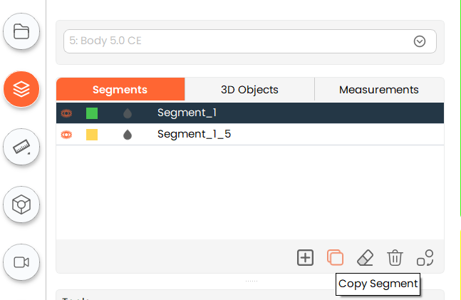
- To create a copy of an existing segment, select the existing segment and click on the "Copy Segment" button.
-
Clear Segment

- Clear any operation performed on a particular segment by clicking on the "Clear Segment" button.
- Clear any operation performed on a particular segment by clicking on the "Clear Segment" button.
-
Delete Segment
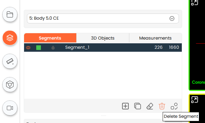
- To delete any existing segment, select the segment you want to delete and click on the "Delete Segment" button.
- To delete any existing segment, select the segment you want to delete and click on the "Delete Segment" button.
-
Convert Segment to Model

- To convert a single segment into a 3D model, click the "Convert Segment to Model" button. To convert multiple segments at once, hold down the
Shiftkey while clicking on the specific segments in the segment table.
- To convert a single segment into a 3D model, click the "Convert Segment to Model" button. To convert multiple segments at once, hold down the
Convert to segment menu:
For model generation, the convert segment to model tool offers three post-processing parameter sets for selection:
-
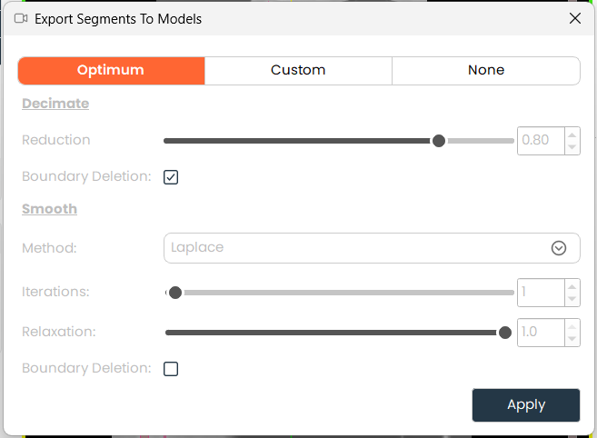
Optimum: Uses factory-validated parameters that strike the best balance between surface smoothness and geometric accuracy. Recommended for all clinical applications
-
Custom Allows manual selection of post-processing parameters for advanced users.
-
Reduction: Sets the percentage by which to reduce the triangle count on the surface mesh. Higher reduction decreases file size and complexity at the cost of detail.
-
Boundary deletion: When enabled, removes mesh points located at the boundary of the model surface.
-
Iterations: Defines how many times the selected post-processing algorithm is applied to the model. More iterations produce smoother results.
-
Methods: Selects the smoothing algorithm used during model generation.
- Laplace
- Relaxation Controls how aggressively each surface point moves toward the average position of its neighbors. Higher values produce a smoother surface.
- Taubin
- Pass band Sets the spatial frequency cutoff for the Taubin smoothing algorithm, which smooths the surface while better preserving volumetric shape compared to Laplace
- Laplace
-
-
None Generates the model directly from the segmentation data without applying any smoothing or mesh optimization
-
Note: Is strongly recommended that Optimum set parameters are utilized for models required for preplanning and diagnosis purposes. Optimum parameters are validated by MySegmenter to ensure accuracy and surface quality are preserved.
-
A dialog will appear where you can choose various settings for the resulting model. The default setting is optimal, but you can change them by clicking the "Custom" tab. Finally, click "Apply" to convert the segment.
-
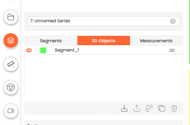
The resulting model is available under "3D Objects" section.
-
-
Export Segments Click the "Export Segments" button to write the current segmentation to disk. The export window offers the following controls:
- Export Type — the output format: DICOM (.dcm); Segmentation (.seg.nrrd), which preserves segment names and colours; NRRD (.nrrd); NIfTI (.nii.gz); or NIfTI (.nii).
- Segments — how much to export: All segments merged into one file, only the Selected segments merged into one file, or Each segment saved as its own separate file. This row is shown for the Segmentation, NRRD, and NIfTI formats and is hidden when DICOM is selected, as it does not apply to DICOM.
When DICOM is selected, every segment in the segment table is exported together in a single file, and a note on screen states this. When NRRD (.nrrd), NIfTI (.nii.gz), or NIfTI (.nii) is selected, the window also shows how many files will be written and the name of each one.
Exported files are named automatically after the segmentation. If a file of the same name already exists in the selected directory, you are asked whether to Overwrite, Keep both, or Cancel; Keep both is the default, so an existing file is not overwritten unintentionally and the new copy is saved under a new number. A success or error message is displayed when the export finishes.
Note: Segmentation (.seg.nrrd) preserves segment names and colours. In the Segments dialog, NRRD and NIfTI write the segmentation as a plain labelmap — an integer mask, without names or colours.
- Import Segmentation
Click the "Import Segmentation" button, located at the end of the row of segment buttons, to bring in an existing segmentation file — .seg.nrrd, .nrrd, .nii, or .nii.gz — and attach it to the volume you are currently working on. The button becomes available once a volume is loaded, as a segmentation always belongs to a volume; if no volume is open, you are prompted to import a volume first.
- If the current segmentation is empty, the imported segments simply fill it in.
- If the current segmentation already contains edits, you are asked whether to Replace it with the imported segmentation, Merge the imported segments into it, or Cancel. Merge is the default, so an existing segmentation is not replaced unintentionally.
- .seg.nrrd files keep their original segment names and colours. Plain .nrrd, .nii, and .nii.gz files are imported as unnamed labels, as those formats do not carry names or colours.
- If the imported segmentation does not line up with the current volume (different dimensions or spacing), it is still imported, but a warning advises that the mask may not align so that the result can be checked.
A success, warning, or error message is displayed when the import finishes.
Note: The buttons in the Segments table appear in the order Convert to Model → Export Segments → Import Segmentation, so the export and import actions sit together at the end of the row.